What Is a Closed Circuit Cooling Tower?
A closed circuit cooling tower — also called a fluid cooler, closed loop cooling tower, or indirect cooling tower — is a heat rejection device that cools process fluid circulating through an enclosed coil or tube bundle without allowing the process fluid to come into direct contact with the outside air or the evaporative spray water. Heat from the process fluid inside the coil is transferred first to a spray water circuit on the outside of the coil, and then that spray water releases heat to the atmosphere through evaporation, just like a conventional open cooling tower. The critical distinction is that the process fluid and the evaporative water remain completely separate throughout — the process fluid flows in a sealed, closed loop that never mixes with external water or air.
This design makes closed circuit cooling towers the preferred solution in applications where the process fluid must remain clean and uncontaminated, where the fluid has high value, where contamination would damage sensitive equipment, or where process fluids such as glycol solutions, oils, or chemical coolants cannot be exposed to open-air evaporative systems. Industries from data centers to steel mills rely on closed loop fluid coolers to maintain precise fluid temperatures while protecting their systems from the fouling, scaling, and contamination risks inherent in open recirculating cooling systems.
How a Closed Circuit Cooling Tower Works
The operating principle of a closed loop cooling tower involves two separate but thermally linked fluid circuits working together to move heat from the process to the atmosphere. Understanding how these circuits interact helps engineers select, size, and operate these units correctly.
The process fluid — water, glycol solution, hydraulic oil, or any other liquid requiring cooling — is pumped from the heat source through the internal coil or tube bundle housed inside the cooling tower. As it flows through the coil, it releases heat through the coil wall to the surrounding environment inside the tower. On the outside of the coil, a spray water system distributes water over the external surface of the coil. This spray water absorbs heat from the coil surface and is simultaneously exposed to a moving airstream generated by the tower's fans. The combination of heat transfer and water evaporation carries the heat away from the coil and exhausts it into the atmosphere. The cooled process fluid exits the coil and returns to the heat source, completing the closed loop. The spray water, now cooled by evaporation, collects in the tower basin and is recirculated by a spray pump back over the coil to repeat the cycle.
Wet Mode vs. Dry Mode Operation
One of the most operationally important features of many closed circuit cooling towers is their ability to switch between wet and dry operating modes. In wet mode — the standard evaporative mode described above — the spray water system is active, providing maximum cooling capacity through the combination of sensible heat transfer and evaporative cooling. In dry mode, the spray water pump is shut off and the unit functions purely as an air-cooled heat exchanger, relying solely on the airstream flowing over the dry coil surface to remove heat. Dry mode consumes no spray water and eliminates evaporative losses and scaling, but provides significantly lower cooling capacity at the same ambient conditions. Many operators switch to dry mode during cooler months when ambient temperatures are low enough that dry-side heat transfer alone is sufficient to meet the cooling load, saving water and reducing chemical treatment costs during those periods.
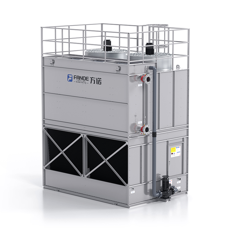
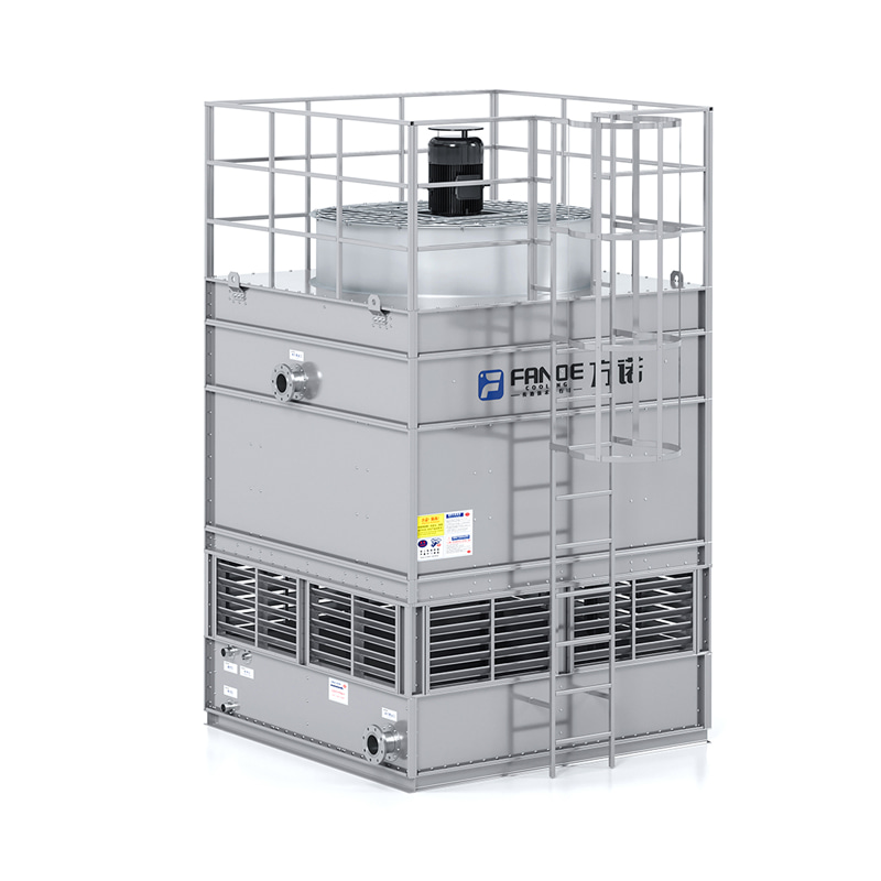
Airflow Configurations: Counterflow vs. Crossflow
Closed circuit cooling towers are built in either counterflow or crossflow airflow configurations. In a counterflow unit, air enters at the bottom of the tower and flows upward through the coil section, moving in the opposite direction to the falling spray water and the downward heat flow — maximizing the thermal driving force between air and spray water. Counterflow closed loop cooling towers tend to be more thermally efficient and have a smaller footprint for a given cooling capacity, but can be taller than crossflow designs. In a crossflow unit, air enters horizontally through the sides of the tower and flows across the coil, perpendicular to the spray water falling over the coil surface. Crossflow designs are often lower in overall height, making them easier to install under height-restricted conditions, and can be easier to access for coil cleaning and maintenance.
Closed Circuit vs. Open Circuit Cooling Tower: Key Differences
Choosing between a closed circuit cooling tower and a conventional open recirculating cooling tower is one of the most fundamental decisions in cooling system design. Each technology has clear strengths and limitations, and the right choice depends on the process fluid characteristics, water quality, maintenance resources, and long-term operating cost priorities.
| Factor |
Closed Circuit Cooling Tower |
Open Circuit Cooling Tower |
| Process fluid protection |
Excellent — fully sealed from external contamination |
None — process water exposed to atmosphere |
| Fouling and scaling risk |
Low on process side; spray circuit needs treatment |
High — open basin exposed to dust, debris, algae |
| Water consumption |
Moderate — slightly higher than open tower |
Lower in wet mode but more variable |
| Capital cost |
Higher — coil and sealed circuit add cost |
Lower for equivalent cooling capacity |
| Heat transfer efficiency |
Slightly lower due to coil thermal resistance |
Higher — direct contact maximizes heat transfer |
| Maintenance complexity |
Moderate — two circuits to manage |
Higher fouling and biological control demands |
| Legionella risk |
Lower — process fluid isolated; spray circuit manageable |
Higher — warm open basin is ideal Legionella habitat |
| Suitability for glycol/special fluids |
Excellent — any fluid can circulate in closed loop |
Not suitable — open basin requires water |
Industries and Applications Where Closed Loop Cooling Towers Excel
Closed circuit cooling towers are specified across a remarkably diverse range of industries and applications, unified by the need to keep process fluid clean, the desire to avoid equipment fouling, or the requirement to cool specialty fluids that cannot be processed through open systems.
Data Centers and IT Cooling
Data centers use closed loop fluid coolers to reject heat from chiller plant condensers or from direct liquid cooling circuits serving server racks. In these facilities, the cooling water quality standards are extremely tight — contaminants in the cooling circuit can damage precision heat exchangers, clog small-bore tubing in liquid-cooled servers, and cause corrosion in aluminum cold plates. A closed circuit cooling tower keeps the cooling water in the data center loop completely clean while still using evaporative cooling to achieve the low approach temperatures needed for efficient chiller plant or free cooling operation.
Industrial Process Cooling
Manufacturing facilities in sectors including plastics injection molding, die casting, hydraulic press systems, induction furnaces, and compressor cooling use closed circuit cooling towers to maintain precise process temperatures. In injection molding, consistent mold cooling temperature directly determines cycle time and part quality — contaminated cooling water would foul mold channels and disrupt temperature uniformity. Closed loop systems protect these precision surfaces while the evaporative cooling tower maintains the fluid temperature set point regardless of ambient conditions.
Steel and Metal Processing
Electric arc furnaces, continuous casting equipment, rolling mill hydraulic systems, and induction heating power supplies all require reliable high-capacity cooling with clean fluid. Mill scale, iron oxides, and metallic dust prevalent in steel plant environments would rapidly foul an open cooling tower basin and damage heat exchanger surfaces. Closed circuit fluid coolers isolate the clean process cooling circuit from the plant atmosphere, providing reliable cooling with manageable maintenance in these harsh environments.
Power Generation and Transformer Cooling
Large power transformers, rectifier sets, and power conversion equipment use closed loop cooling systems where transformer oil or deionized water must circulate in a fully sealed circuit. Contamination of transformer oil is catastrophic — it degrades insulation properties and can cause transformer failure. Closed circuit cooling towers serve as the heat rejection point for the secondary cooling circuit, keeping the process fluid clean while reliably managing the thermal load around the clock.
HVAC Chiller Plant Free Cooling
In commercial and industrial HVAC systems, closed circuit cooling towers are used in economizer or free cooling configurations where the chilled water loop is pre-cooled or fully cooled by the outdoor air during cold weather without running the mechanical chiller compressors. A fluid cooler connected directly into the chilled water loop — or via a heat exchanger — can provide full free cooling when ambient wet-bulb temperatures are sufficiently low, eliminating chiller compressor energy during those periods and delivering substantial annual energy savings.
Sizing a Closed Circuit Cooling Tower: What You Need to Know
Proper sizing of a closed loop cooling tower is critical to ensuring the unit meets the process cooling load under the worst-case ambient conditions your site experiences. Undersizing results in process fluid temperatures exceeding limits; oversizing wastes capital and can lead to operational control issues at partial load. The following parameters must be defined before selecting a unit:
- Heat rejection load (kW or tons of refrigeration): The total heat that the cooling tower must remove from the process fluid at peak conditions. This includes not just the process heat load but also any pump heat added to the fluid in the closed loop circuit.
- Process fluid inlet and outlet temperatures: The temperature of the fluid entering the coil from the process (hot side) and the required temperature leaving the coil (cold side). The difference is the fluid temperature range, and together with the flow rate, it defines the heat load.
- Design wet-bulb temperature: The closed circuit cooling tower's capacity is governed by the ambient wet-bulb temperature, not dry-bulb. The design wet-bulb temperature is the highest wet-bulb temperature expected at your site for a defined number of hours per year — typically the 1% or 0.4% design condition from ASHRAE climate data for the nearest weather station.
- Approach temperature: The difference between the cooled fluid outlet temperature and the ambient wet-bulb temperature at design conditions. Smaller approach temperatures require larger, more expensive units. Typical approaches range from 3°C to 8°C in standard industrial applications — tighter approaches are achievable but at significantly higher capital cost.
- Process fluid type and concentration: If the process fluid is a glycol-water mixture rather than pure water, the heat transfer coefficient inside the coil is reduced compared to pure water, and the unit must be sized accordingly. Provide the fluid type, concentration, and design temperature to the manufacturer for accurate sizing.
- Fouling factor allowance: A fouling factor accounts for the gradual reduction in coil heat transfer performance over time due to scale or biofilm buildup on the coil exterior. Standard design fouling factors are published in TEMA standards — include the appropriate factor in thermal sizing to ensure the unit meets requirements throughout its service life, not just when new.
Water Treatment for Closed Circuit Cooling Tower Systems
Although the process fluid in a closed circuit cooling tower is isolated from the atmosphere, the spray water circuit that wets the exterior of the coil is an open evaporative system that concentrates dissolved minerals and supports biological growth — and it requires active water treatment just like a conventional open cooling tower basin.
Spray Water Circuit Treatment
As spray water evaporates, dissolved solids including calcium, magnesium, and silica remain behind and concentrate in the basin. Without blowdown and chemical treatment, these minerals deposit as scale on the exterior surface of the coil — exactly where heat transfer must occur — dramatically reducing thermal performance and potentially causing under-deposit corrosion. A scale and corrosion inhibitor program appropriate for the local water chemistry, combined with controlled blowdown to limit cycles of concentration, is essential for maintaining coil cleanliness and unit performance.
Biological Control and Legionella Management
The warm, nutrient-rich spray water basin of a closed circuit cooling tower is a potential growth environment for Legionella bacteria and other microorganisms. A biocide program — typically alternating oxidizing biocides such as chlorine or bromine with non-oxidizing biocides — must be maintained to control biological populations. In many jurisdictions, closed circuit cooling towers are subject to the same Legionella risk assessment, water management plan, and testing requirements as open cooling towers. Regular ATP testing or culture testing of the spray water verifies biological control program effectiveness. Maintaining spray water pH between 6.5 and 8.5 and keeping total dissolved solids below recommended limits also supports biological control.
Closed Loop Process Fluid Treatment
Although the closed process loop is sealed, it still requires its own water treatment program. Corrosion inhibitors appropriate for the metals in the circuit — typically a molybdate or nitrite-based inhibitor for mixed metallurgy systems — must be maintained at specified concentrations. For glycol-based systems, the glycol concentration and inhibitor package must be checked and replenished periodically, as inhibitors deplete over time and glycol can degrade to acidic byproducts that accelerate corrosion if left unchecked. Annual chemical analysis of the closed loop fluid is the minimum recommended maintenance interval.
Maintenance Tasks That Keep a Closed Loop Cooling Tower Running Reliably
Closed circuit cooling towers are relatively low-maintenance compared to open towers — the sealed process circuit eliminates many contamination and fouling concerns — but regular attention to the spray water system, mechanical components, and coil condition is essential for sustained reliable performance.
- Spray nozzle inspection and cleaning: Spray nozzles distribute water evenly over the coil surface. Plugged or worn nozzles create dry spots on the coil where scaling and over-temperature can occur. Inspect and clean spray nozzles at least twice per year — more frequently in hard water areas. Replace nozzles showing wear or deformation that affects spray pattern uniformity.
- Coil exterior cleaning: Scale, biofilm, and airborne debris accumulate on the exterior surface of the heat transfer coil over time. An annual high-pressure water wash — and chemical descaling if hard scale has formed — restores coil cleanliness and heat transfer performance. Access panels and sufficient clearance around the unit are important design considerations that make coil cleaning practical.
- Basin cleaning and sediment removal: Suspended solids settle in the spray water basin as sludge. Accumulated sludge harbors bacteria, accelerates corrosion at the basin floor, and clogs the spray pump strainer. Clean the basin and remove sludge at each seasonal startup or annually at minimum. Install a side-stream filtration system if the local environment introduces significant airborne dust or debris into the basin.
- Fan and drive system inspection: Inspect fan blades for erosion, corrosion, or balance issues — imbalanced fans cause bearing wear and structural vibration. Check belt tension and condition on belt-drive units. Verify gear oil level and condition on gear-drive units. Lubricate fan shaft bearings per the manufacturer's schedule. Check motor insulation resistance annually.
- Drift eliminator inspection: Drift eliminators capture water droplets carried by the exhaust airstream, preventing water loss and reducing the risk of Legionella-laden aerosols leaving the tower. Inspect drift eliminators for damage, clogging, or displacement at each annual service. Damaged drift eliminators increase water consumption and regulatory non-compliance risk.
- Winter freeze protection: In cold climates, the spray water basin and piping must be protected from freezing when the unit is shut down or operating at reduced load in cold weather. Verify that basin heaters, heat tracing on exposed piping, and low-ambient control sequences are functional before the first frost of the season. For extended cold-weather shutdowns, drain the spray water circuit completely.
Common Problems with Closed Circuit Cooling Towers and How to Fix Them
Even well-maintained closed loop cooling towers develop performance issues over time. Recognizing the symptoms and their root causes enables rapid response before minor issues become costly failures.
Reduced Cooling Capacity or Rising Process Fluid Temperatures
If the process fluid outlet temperature is rising above the design setpoint under conditions that previously kept it within limits, the most common causes are scale buildup on the coil exterior reducing heat transfer, plugged spray nozzles creating dry spots, reduced spray water flow from a worn pump or clogged strainer, fan performance degradation from worn blades or a slipping belt, or the ambient wet-bulb temperature exceeding the design value. Check each of these systematically: verify spray pump flow rate, inspect nozzles, check fan speed and blade condition, then clean the coil if no mechanical issue is found.
Excessive Water Consumption and Makeup Water Use
Higher-than-expected makeup water consumption points to excessive blowdown, leaks in the spray water piping or basin, high drift losses from damaged drift eliminators, or the float valve not closing correctly and allowing overflow. Meter the makeup water flow and compare it to the theoretical evaporation rate based on heat load — if makeup significantly exceeds evaporation plus controlled blowdown, a leak or mechanical fault is the likely cause.
Coil Corrosion or Leaks
Pinhole leaks in the heat transfer coil allow spray water to enter the closed process loop — detectable by a rising conductivity or change in chemistry of the closed loop fluid. Coil corrosion is caused by aggressive spray water chemistry (low pH, high chloride, insufficient inhibitor), galvanic corrosion at dissimilar metal connections, or microbiologically influenced corrosion (MIC) from biofilm under-deposit attack. Address water chemistry immediately, locate and repair the leak, and review the biocide and inhibitor program to prevent recurrence.


 Eng
Eng
 Cos'è una torre di raffreddamento a circuito aperto e come funziona?
 Che cos'è una torre di raffreddamento di tipo chiuso e quando dovresti usarne una?Come funziona effettivamente una torre di raffreddamento di tipo chiuso A torre di raffreddamento di tipo chiuso — ampiamente d...
 Guida alle torri di raffreddamento: tipi, come funzionano e criteri di selezioneCome funziona realmente una torre di raffreddamento Una torre di raffreddamento è un dispositivo di smaltimento del calore che rimuove il calore...
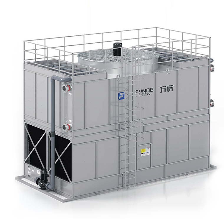 Torri di raffreddamento industriali: come funzionano, tipi e come farle funzionare correttamenteCosa fanno le torri di raffreddamento industriali e perché sono importanti Le torri di raffreddamento industriali sono grandi sistemi di smalti...
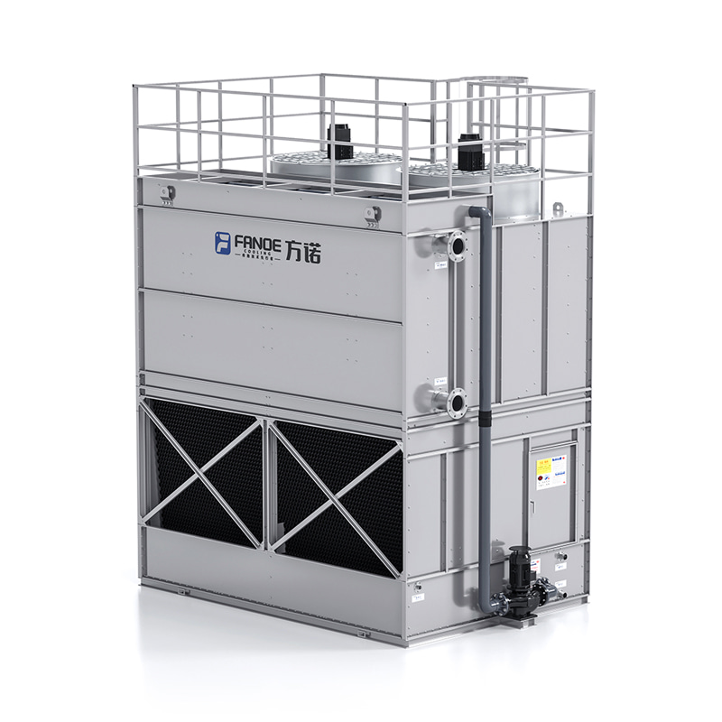 Spiegazione del condensatore evaporativo: come funziona, come sceglierne uno e come mantenerlo in funzioneCos'è un condensatore evaporativo e come funziona? Un condensatore evaporativo è un dispositivo di smaltimento del calore che combina le fu...